|
|
 |
|
|
All of these modules will be connected through a CAN (Controller Area Network) bus, running throughout the robot. They will also each have their own dedicated microcontroller. The goal is that systems requiring a decent amount of low-level real-time control will not be a burden on the CPU module, either in terms of needing cycle time, or in terms of code responsibility. Another advantage of this approach is ease of upgrading. The robot's hardware can evolve over time, and major systems can be swapped in and out with minimal modification to the rest of the robot. Furthermore, all these modules could theoretically be produced in quantity and reused in other robot designs.
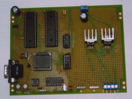
My implementation begins by using a Motorola 68HC11E2 microcontroller as the
I/O controller. Then, I use a pair of Agilent HCTL-1100 motion control chips
for the PWM and closed-loop. While rather expensive, these chips are worth it.
They take all the hassle out of the motion control problem, which is the
foundation of any robot's controllable mobility.
|
|
|
|
|
|
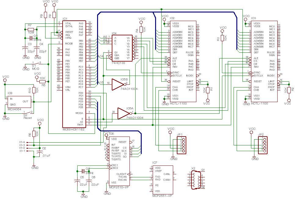
Below is the schematic of the hardware I have currently built. So far, it has only been tested on the workbench. The software will be written in assembler, and will be posted once complete. The current code on the board is just test code to exercise some of the functionality of the HCTL-1100 chips independently of external commands.
Schematic of drive controller
Note: This schematic mostly reflects the actual hardware that I have built.
The major differences include 0.1uF bypass capacitors across most of the IC's
power pins, and the H-Bridge circuitry using Infineon TLE5206 chips. The
former isn't functionally relevant and thus may remain omitted. The latter
will be added eventually. In addition, the wiring for the CAN chips is
incomplete, and will be updated once I finish that part of the
board and have the ability to test it.
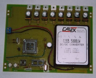
At the core of any robot system is an electrical power source. Usually one simply needs a regulated 5V source for the electronics and something less specific in the 12-24V range for the motors and sometimes other systems. Normally, this is accomplished through some simple regulators, without much control. In this project, however, I have decided to build a whole dedicated controller for the task. The idea is that the power controller will have the final say as to whether the robot is functioning. It will be the only module directly switched on by the power switch.
The power needs of "Chip III" will be satisfied by multiple independently
controlled 5V lines, a lower-current 12V source, and an unregulated 18V feed
directly off the battery system for the drive motors.
|
|
 |
|
|
|
|
|
Project overview My tools and equipment The robot! Links |