|
|
The brains of the robot are based around the MaxMaster package of the SUPER-TCOMP single board computer. This unit made by Ray Butts, is the most versatile system I've seen that is based on Motorola's 68HC11 microcontroller.
I've just completed my own expansion board that plugs into the bus of my SUPER-TCOMP, and allows me to add many memory mapped devices. This device was inspired by the need for lots of parallel I/O I saw when looking at the specs for a speech board I wanted. I'm currently using it to interface a big 4x40 backlit LCD display, a digital output port (you never can have enough), and the V8600 speech board.
Super-EXP Schematic - allows up to 16 parallel I/O devices to be memory mapped from $6000 to $6F00
|
|
|
|
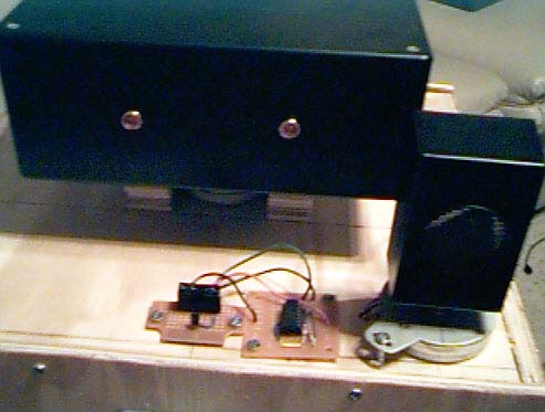 |
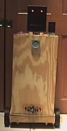
| Here you can see the top of the robot's body. Notice the ultrasonic
transducer on
a stepper motor and a temperature sensor with an op-amp chip next to it. The robot's old head is in this picture. I've since replaced it with a newer unit as seen in the other pictures. |
|
|
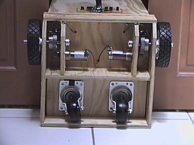 |
| Here you can see the robot's underside. This is where the simple
drive train assembly is housed. The robot uses two 24VDC gearhead Pittman motors that drive a pair of 6" lawnmower wheels. |
|
|
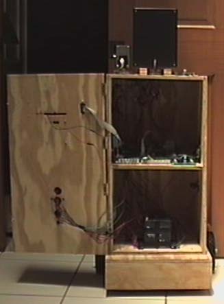 |
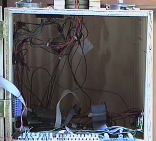
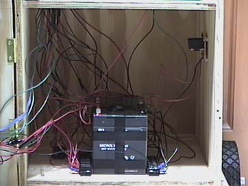
| This is a basic picture of the inside of the robot.
I build the robot body with plans for two main section, top and bottom. I have more detailed information on these sections below. |
|
|
|
|
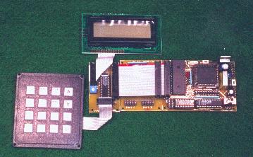 |
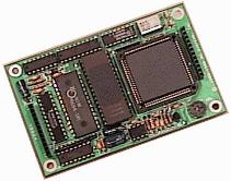
| This is the 68HC11 based microcontroller board that I use
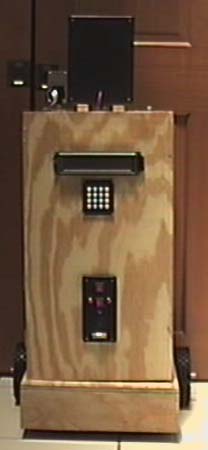
as the robot's brain. It contains a 68HC11E1, a 32k SRAM memory chip with a 10 year backup battery, a 68HC24 Port Replacement Unit, and a display/keypad module. I am currently using the keypad as the input device on the back of the robot, however I replaced the display with a larger unit interfaced through my own expansion board. In the future, I might install this old display elsewhere on the robot as a mini status monitor or something. |
| V8600 Speech Synthesis Board |
 |
| All good robots need to talk, right?
Well, I thought so too. Therefore, I got this neat little piece of equipment. Through this board, my robot can talk, generate DTMF tones, and even make musical notes! It was easy to interface it to my expansion board, and wasn't too hard to get working. |
|
|
|
Project overview My tools and equipment The robot! Links |